Описание
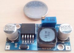
модуль MP3 YX6300 YX5300 UART плеер для Ардуино
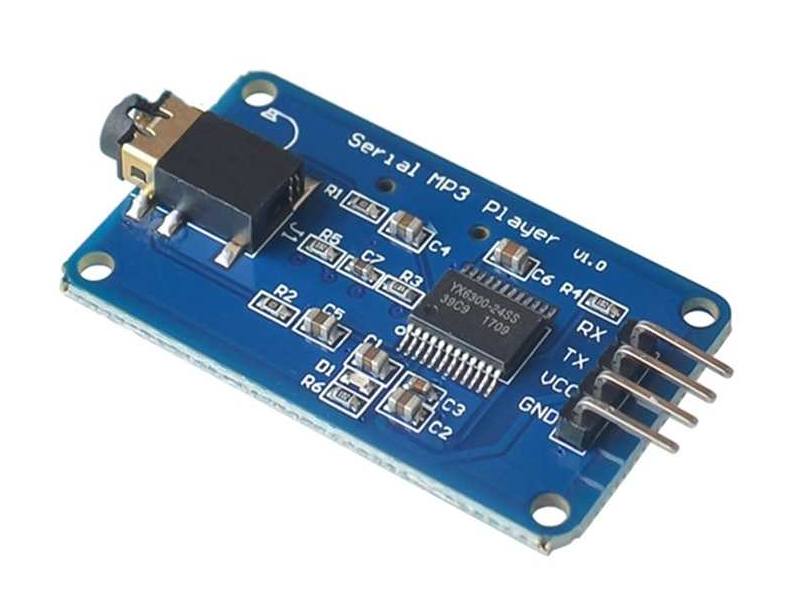
While browsing eBay looking for a module to play extended sound effects (MP3 and WAV files), I came across these modules that looked like they would fit my purpose. The module has been around for a few years and is based on the YX5300 IC. As it turns out they are easy to use and produce a good sound in a small package.
The downside is that there is not a huge lot of documentation for the board and the original is in Chinese. A copy of the official documentation I was able to find can be reached through this link.
While it is easy to make the board play a sound, there are no examples (that I could find) of ‘advanced’ control of the board in a system multitasking other control tasks. So I decided to write a control library that would provide me with the interface I thought was needed. The library (MD_YX5300) can be found at on my code repository.
Hardware Specifications
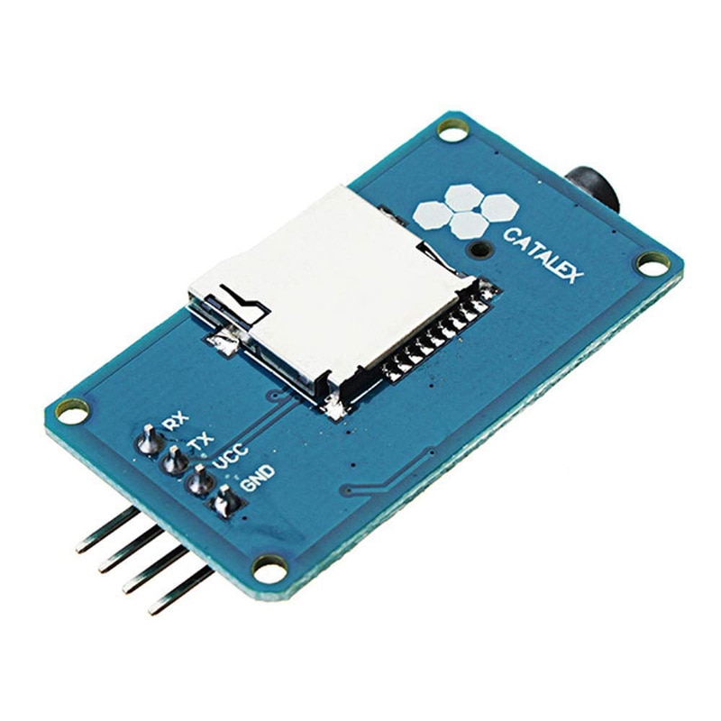
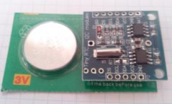
The YX5300 supports 8kHz to 48kHz sampling frequency MP3 and WAV file formats. The audio files are stored on a micro SD card that plugs into a TF card socket on the back of the board.

The MCU controls the device playback by sending serial commands through a TTL level UART control interface (GND, VCC, TX, RX). Pins are connected GND to MCU ground, VCC to 5V power supply, YX5300 TX (transmit) to the designated RX (receive) pin for the library, YX5300 RX to TX. The MCU RX/TX can be hardware serial pins or a software controlled serial port.
Sound is output through a headphone jack to headphones or an external amplifier. The board has a playback indicator LED that blinks during playback and is steady otherwise.
The TF card socket on the PCB reverse is for plugging in the micro SD card with MP3/WAV files. The micro SD card should be formatted as FAT16 or FAT32 and songs must be prefixed with a unique 3 digit index number (for example, 001xxx.mp3, 002xxx.mp3, 003xxx.mp3, etc, where xxx is an arbitrary optional name. Songs may also be grouped in folders named ’01’, ’02’, ’03’, etc. An example folder and file structure on the micro SD card might look like:
+-+- 01
  | + 001-Happy_Dance.mp3
  | + 002-O_Sole_Mio.mp3
  |
  +- 02
  | + 003-Humpty_Dumpty.mp3
  | + 004-Incy_Wincy_Spider.mp3
  | + 005-Grand_Duke.mp3
  |
  +- 03
    + 006-Fernando.mp3
    + 007-Mamma_Mia.mp3
Songs are referenced by folder and by song ‘index’, although it seems that the numeric index is sometimes ignored and the songs played in the order they are stored in the SD card. The documentation is unclear on this and seems to imply both situations. So, even if you plan only one playlist, it is better to keep them in a ’01’ folder and save all the songs to the SD card at the same time.
Communicating with the Module
Communications is via asynchronous serial RS232 at 9600 bps, 8 data bits, No parity, 1 stop bit, no hardware flow control. Flow control is implemented using a request/response protocol with data packets in the following byte format:

where the fields have the following meaning:
- Start (0x7e) and End (0xef) mark the start and end of the serial packet. A receiver should synchronize on the start byte and read the packet to the end.
- Version is always 0xff. I assume this is to cater for future changes in the protocol and would allow comms software to adjust dynamically.
- Length is the number of bytes between the Start byte and Checksum. In this implementation it is always 6 bytes (the lighter colored boxes).
- Cmd (Command) in a request message is the control function code and in a response is error/status code.
- Fback (Feedback) is set to 1 to receive a request acknowledgement, or 0 for no acknowledgement.
- DataHi and DataLo are the high and low bytes of the command modifier or the status/error code. They are set to suit the Cmd byte (see the tables below).
- ChkHi and ChkLo are the checksum high and low bytes. The checksum is optional and can be omitted from requests messages, but a response from the device always includes the checksum field. The checksum is calculated as the two’s complement of the 16-bit sum of the bytes between Start and Checksum (ie, the same as those counted in Length).
The module can also initiate sending a message to the MCU when certain events occur (an ‘unsolicited’ message). These are received and processed without a matching prior request.
Device Commands
The interesting elements of the protocol message are the Cmd and Data fields.
The Cmd field allows us to control the module. The official English documentation provides a set of valid command codes and the Chinese documentation provides an additional set of codes. All the commands I have discovered are collated in the table below. Where the data field is required this is noted, otherwise it is set to zero and ignored.
| NEXT_SONG | 0x01 | Play next song. |
| PREV_SONG | 0x02 | Play previous song. |
| PLAY_WITH_INDEX | 0x03 | Play song with index number. Data is the index of the file. |
| VOLUME_UP | 0x04 | Volume increase by one. |
| VOLUME_DOWN | 0x05 | Volume decrease by one. |
| SET_VOLUME | 0x06 | Set the volume to level specified. Data is the volume level [0..30]. |
| SET_EQUALIZER | 0x07 | Set the equalizer to specified level. Data is [0..5] – 0=Normal, 1=Pop, 2=Rock, 3=Jazz, 4=Classic or 5=Base. |
| SNG_CYCL_PLAY | 0x08 | Loop play (repeat) specified track. Data is the track number. |
| SEL_DEV | 0x09 | Select file storage device. The only valid choice for data is TF (0x02). |
| SLEEP_MODE | 0x0a | Chip enters sleep mode. |
| WAKE_UP | 0x0b | Chip wakes up from sleep mode. |
| RESET | 0x0c | Chip reset. |
| PLAY | 0x0d | Playback restart. |
| PAUSE | 0x0e | Pause playback. |
| PLAY_FOLDER_FILE | 0x0f | Play the file with the specified folder and index number |
| STOP_PLAY | 0x16 | Stop playback. |
| FOLDER_CYCLE | 0x17 | Loop playback within specified folder. Data is the folder index. |
| SHUFFLE_PLAY | 0x18 | Playback shuffle mode. Data is 0 to enable, 1 to disable. |
| SET_SNGL_CYCL | 0x19 | Set loop play (repeat) on/off for current file. Data is 0 to enable, 1 to disable. |
| SET_DAC | 0x1a | DAC on/off control (mute sound). Data is 0 to enable DAC, 1 to disable DAC (mute). |
| PLAY_W_VOL | 0x22 | Play track at the specified volume. Data hi byte is the track index, low byte is the volume level [0..30]. |
| SHUFFLE_FOLDER | 0x28 | Playback shuffle mode for folder specified. Data high byte is the folder index. |
| QUERY_STATUS | 0x42 | Query Device Status. |
| QUERY_VOLUME | 0x43 | Query Volume level. |
| QUERY_EQUALIZER | 0x44 | Query current equalizer (disabled in hardware). |
| QUERY_TOT_FILES | 0x48 | Query total files in all folders. |
| QUERY_PLAYING | 0x4c | Query which track playing |
| QUERY_FLDR_FILES | 0x4e | Query total files in folder. Data is the folder index number. |
| QUERY_TOT_FLDR | 0x4f | Query number of folders. |
The error/Status values returned from the device are also listed below. The Data field usually contains the status value or data requested.
| TF_INSERT | 0x3a | TF Card was inserted (unsolicited message). |
| TF_REMOVE | 0x3b | TF card was removed (unsolicited message). |
| FILE_END | 0x3d | Track/file has ended (unsolicited message). Data is the index number of the file just completed. |
| INIT | 0x3f | Initialization complete (unsolicited message). Data is the file store types available (0x02 for TF). |
| ERR_FILE | 0x40 | Error file not found. Data is error code (no definition). |
| ACK_OK | 0x41 | Message acknowledged ok |
| STATUS | 0x42 | Current status. Data high byte is file store (2 for TF); low byte 0=stopped, 1=play, 2=paused. |
| VOLUME | 0x43 | Current volume level. Data is volume level [0..30]. |
| EQUALIZER | 0x44 | Equalizer status. Data is equalizer mode types 0=Normal, 1=Pop, 2=Rock, 3=Jazz, 4=Classic or 5=Base. |
| TOT_FILES | 0x48 | TF Total file count |
| PLAYING | 0x4c | Current file playing |
| FLDR_FILES | 0x4e | Total number of files in the folder. Data is the number of files. |
| TOT_FLDR | 0x4f | Total number of folders. Data is the number of folders. |
So why use a Library?
The MD_YX5300 library encapsulates each of the command messages as a class method. At its most basic, the library allows the processing of messages in the background while the application goes about its other business. This is done with a polling mechanism (check()) called once per loop() cycle.
The library can operate in synchronous or asynchronous mode. In synchronous mode, a call that sending a request message will include waiting for the response before returning, allowing a simple flow in the main application provided it can tolerate the delays. This would satisfy most of the applications that I was able to find as examples.
Alternatively, asynchronous mode can be used, where the response can be processed by the application at a later stage. This is triggered by check() returning value signalling a message (response or unsolicited) is waiting.
Additionally, by defining a callback function, the application will be ‘called back’, including response status, when any message is been received. The callback approach particularly suits applications implemented as Finite State Machines.
Having this flexibility to tailor the programmer’s approach greatly simplifies handling the relatively slow serial comms link without losing efficiency in the rest of the application.
Update: More information on Message Sequencing for the YX5300 in this blog.

Отзывы
Отзывов пока нет.